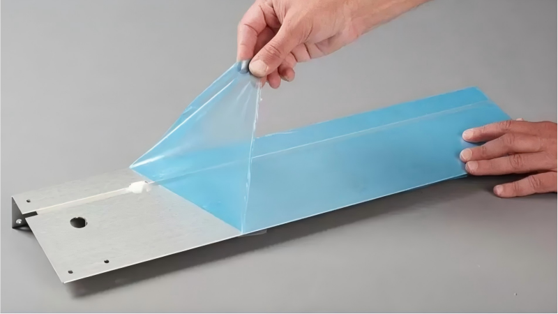
Insulation tape in an EV battery pack may provide dielectric separation, abrasion protection, component holding, masking, or process protection. The term ‘battery tape’ therefore covers different functions, and each function needs its own material and validation requirements.
Selection should begin with where the tape is used, what failure it must prevent, and which manufacturing steps it must survive. A single headline temperature or voltage value is not enough.
Cell or module electrical insulation
Busbar, edge, or sharp-feature protection
Harness bundling and abrasion resistance
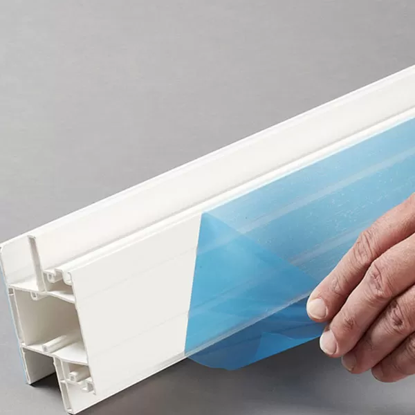
Temporary process masking or surface protection
Gap control, labeling, or traceability
Die-cut insulating pads or wraps
Donlee's EV battery insulation tape should be matched to the declared role. Temporary protection film and permanent electrical insulation should not be treated as the same qualification.
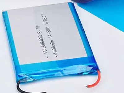
Review dielectric strength, breakdown voltage, insulation resistance, and comparative tracking or flammability data where relevant. A breakdown voltage belongs to a particular tape thickness and test method; it cannot be transferred to a thinner construction without evidence.
Consider edges, overlaps, wrinkles, and puncture risk. The installed geometry may have lower effective protection than a flat laboratory specimen.
Ask about continuous operating temperature, short process peaks, cold exposure, and thermal cycling. The adhesive and backing can respond differently: a backing may remain intact while adhesion drops or residue increases.
Test after the actual curing, welding-adjacent, aging, or environmental cycle. If the tape is near a heat-generating component, include the local temperature and duration rather than only the ambient pack temperature.
Battery components can include aluminum, copper, coated metals, engineering plastics, foams, and composite surfaces. Cleaners, electrolytes, coolants, or plasticizers may also be present. Evaluate adhesion and material change on the exact substrate after realistic exposure.
Surface energy, contamination, and roughness affect bond. Define cleaning and application conditions so a laboratory result can be reproduced on the line.
| Process factor | What to verify |
|---|---|
| Die cutting | Edge quality, adhesive ooze, liner release, and registration |
| Pick and place | Part flatness, static, release force, and vision contrast |
| Lamination | Pressure, speed, temperature, and bubble control |
| Traceability | Lot, roll, slit, and die-cut batch identification |
| Rework | Removal method, residue, and substrate damage |
A material that passes electrical tests but jams an automated line is not production-ready. Run equipment trials at target speed and include changeovers.
Automotive programs may require controlled specifications, PPAP-related evidence, material declarations, restricted-substance compliance, lot traceability, and formal change notification. Confirm which documents apply to the exact tape code and manufacturing location.
Approve a control plan for coating, thickness, adhesion, appearance, slitting, and packaging. Retained samples and lot records make failure analysis faster.
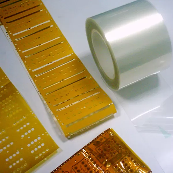
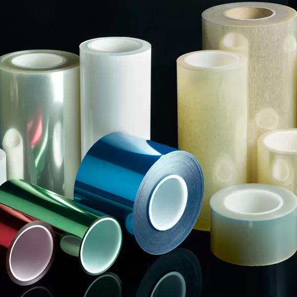
The choice may include PET, polyimide, nonwoven, or other engineered constructions depending on electrical, thermal, mechanical, and process needs. Define the function first.
They are related but reported differently. Breakdown voltage applies to the specimen, while dielectric strength is often normalized by thickness. Check the test method and units.
No. Backing temperature capability and adhesive aging are different. Validate removal or permanent bonding after the real thermal profile.
Include function, substrate, geometry, thickness, electrical/thermal requirements, environmental exposure, process, automation, documentation, quantity, and change-control needs.
Donlee can review application and process data to propose sample constructions. Final approval should cover electrical, thermal, chemical, mechanical, and manufacturing performance on the actual component geometry.